Decoding M12 Connectors: A Practical Guide for IO-Link Applications
Avoid downtime and costly mistakes by choosing the right M12 connector for your IO-Link systems

Reading Time: minutes
In factory automation, few issues can cause more on-site problems than using the wrong cable or connector. One common source is the M12 connector – not due to its faulty design, but because its many coding variations are often misunderstood. “M12” refers to the 12 mm metric locking thread, standardized under IEC 61076-2-101. Whether you're connecting IO-Link sensors, setting up distributed I/O, or integrating power into a control system, choosing the correct M12 coding is critical.
Understanding M12 coding types and their functions
Each M12 coding type is designed for a specific function, whether it’s connecting sensors and actuators, supplying power, or supporting Ethernet-based communication. Confusing one coding type can lead to downtime, equipment damage, or failed installations.
It's also important to understand that, in most cases, it’s the devices, not the engineers, that determine which M12 connector/cable is required. By understanding the different code types, you can ensure the right connectors and cables are stocked and available when needed. A mismatch between device requirements and available inventory is one of the most common causes of installation delays.
The guide covers the most common M12 code types used in IO-Link systems: A, B, L, T, D, and X-coded. We’ll explain the purpose of each code, how to identify it, and how to avoid costly mistakes. Use it not only to select the right connector, but also to assess your current inventory and ensure you're prepared to meet the needs of your facility.
Overview of common M12 code types in IO-Link systems
Code | Pin Count | Typical Use | Notes | Keying and Pinout |
A-coded | 3, 4, 5 | Sensors, actuators, and IO-Link devices | Most common IO-Link coding; supports analog/digital I/O and IO-Link communication. |
|
B-coded | 5 | Profibus, legacy fieldbus | Rare in modern IO-Link; sometimes used for dual-channel power. |
|
L-coded | 5 (4+PE) | High-power DC (up to 16 A) | For IO-Link network blocks and distributed I/O requiring higher current. |
|
T-coded | 4 (2x power pairs) | Power transmission (up to 12 A continuous) | Dedicated power-only connector. |
|
D-coded | 4 | Ethernet (100 Mbps) | For standard industrial Ethernet (not for IO-Link directly). |
|
X-coded | 8 | Ethernet (up to 10 Gbps) | For high-speed data transmission. Often used in hybrid setups with IO-Link + vision or high-speed data applications. |
|
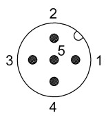
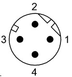
A-Coded: The workhorse of IO-Link: Typically featuring 3, 4, or 5 pins, A-coded connectors are the most common and versatile option for IO-Link ports and devices. They are used for sensors, actuators, standard IO-Link communication, supporting digital IO-Link ports and devices. A-coded connectors are versatile, supporting digital I/O, analog sensors, and IO-Link protocol. Pin 4 is typically the C/Q communication line. Use A-coded connectors for nearly all standard IO-Link device connections unless higher power requirements exist.
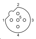
B-Coded: The legacy fieldbus player: With a 5-point configuration, B-coded connectors are primarily Profibus and some dual-channel power setups. They feature different keying to prevent cross-mating with A-coded plugs. Rarely seen in modern IO-Link installations, B-boded connectors are mostly found in legacy systems or where isolated dual power sources are required. Unless you're integrating with older Profibus equipment, these connectors are typically unnecessary.
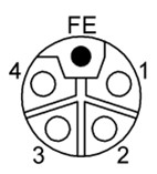
L-Coded: Powering IO-Link hubs and more: Featuring 5 pins (4 + PE), L-coded connectors are designed for high-current DC power applications, supporting up to 16 A. As IO-Link masters and hubs become more advanced and power-demanding in applications, these connectors are becoming increasingly common. They offer compact, high-current delivery with mechanical keying to prevent misconnection. Ideal for supplying power to IO-Link masters and field I/O blocks.
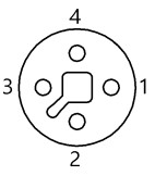
T-Coded: Dedicated power distribution: With a 4-pin configuration, T-coded connectors are built specifically for power-only connections, handling up to 12 A continuous. They’re not used for communication, only power, making them ideal for distributing clean power to actuators, lights, or field devices. They are typically found only on devices that specifically require them, such as certain network blocks or field devices designed for this type.
D-Coded: Ethernet for industrial use: Featuring 4 pins, D-coded connectors support 100 Mbps Industrial Ethernet and are frequently used alongside IO-Link for PLC communications, IO-Link masters with Ethernet/IP or Profinet, and HMI or SCADA interfaces. While not used for IO-Link itself, they are the standard for Ethernet connectivity in industrial environments. Important to note: D-coded connectors are strictly for Ethernet communication, not IO-Link.
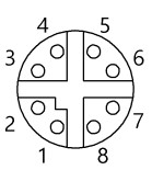
X-Coded: High-speed data backbone: With 8 pins, X-coded connectors support Gigabit Ethernet up to 10 Gbps, making them ideal for applications requiring high-speed data alongside IO-Link, such as machine vision, edge computing, or centralized data logging. They provide high EMI resistance and superior bandwidth in harsh environments. Use X-coded when high-throughput networking must coexist with your IO-Link system.
Using this guide for field reference and inventory planning
Use this guide as both a quick field reference and a tool for inventory planning. Take the time to assess your existing stock: Do you have the right mix of M12 connectors and cables to support the devices in your facility today and in the future?
And when in doubt, don’t guess, decode.