

Selecting Inductive Sensors for Welding Applications
Pick the best sensor for your harsh welding application.
Reading Time: minutes
Selecting the right inductive welding sensor
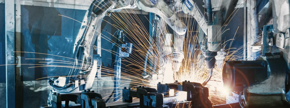
Inductive sensors are commonly used to provide non-contact metallic object detection in fixtures, tooling, and material-handling equipment. They are well suited to industrial automation, but welding applications can be challenging due to electromagnetic fields, weld spatter, mechanical impact, ferrite dust, heat, cable damage, and restricted mounting space.
While selecting the right inductive sensor for welding can seem daunting, a few key considerations can streamline the process. Start by reviewing the application and answering a few questions:
How will the sensor be used?
What environment will it be exposed to?
Are there similar applications and are the sensors failing – if “yes”, why/how are they failing?
How will the sensor be used?
Consider what is being detected, the environment and the space available to install the sensor.
Target object material
General purpose inductive sensors detect steel, aluminum, copper, brass, nickel, or other metals but “switch” at different distances depending on the material, therefore a correction factor needs to be applied. Special sensors can be selected to only detect ferrous materials (“selective ferrous” sensors for ferromagnetic steel and iron) or to only detect non-ferrous materials (“selective non-ferrous” sensors for aluminum, copper, brass and some stainless steels). There are also special “Factor 1” sensors which have identical switching distances regardless of the material and therefore do not need a correction factor.
|
Material |
Standard |
Factor 1 |
Selective Ferrous |
Selective Non-ferrous |
|
Steel |
1.00 |
1.00 |
1.00 |
0.00 |
|
Copper |
0.25 – 0.45 |
1.00 |
0.00 |
1.10 |
|
Brass |
0.35 – 0.50 |
1.0 |
0.00 |
0.90 |
|
Aluminum |
0.30 – 0.45 |
1.00 |
0.00 |
1.00 |
|
Stainless Steel |
0.60 – 1.00 |
1.00 |
0.10 – 0.70 |
0.00 |
Typical correction factors by target material and sensor type. Values vary by design and manufacturer.
Target object size and orientation
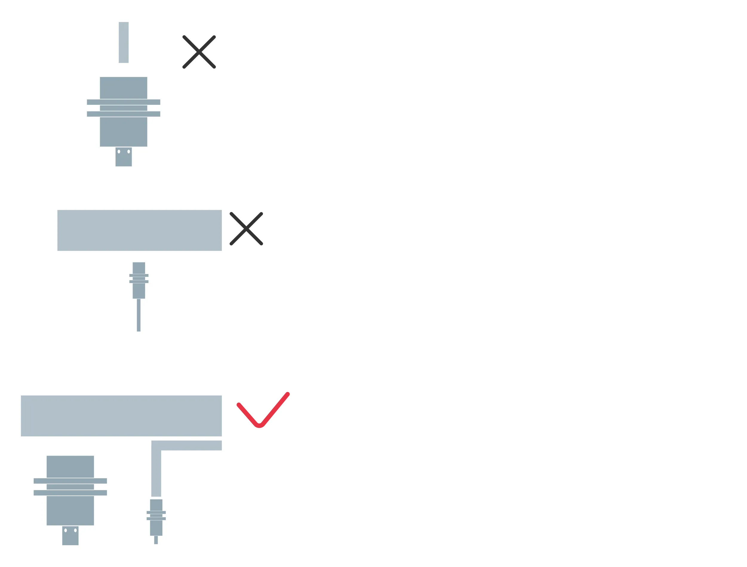
The target should adequately cover the active sensing face. Larger sensors generally offer more sensing range and can be mounted farther from large, heavy parts, reducing impact risk. The challenge, however, is that a large sensor will have difficulty detecting a part edge and a mini sensor is therefore recommended for edge detection applications. (Read more about mini sensors in What Makes Mini Block Inductive Sensors Unique?.)
 Environment
The environment plays a strong role in welding applications and can dramatically affect sensor performance and life. Many applications are subject to strong electromagnetic welding fields, weld spatter, ferrite dust, part impact, and/or high temperature.
Welding equipment can generate strong electromagnetic fields which interfere with sensor operation and cause false switching or signal “chatter.” If the sensor is close enough to be affected, select a design which is designated as weld/magnetic field immune (WFI).
Sensors used near parts being welded are often subject to welding debris, weld spatter or ferrite dust. Protective sensor coatings are available to resist weld spatter accumulation and simplify spatter removal. These surface coatings range from basic (PTFE, ceramic faces) to high performance (Sun 73, Fortron® PPS). For issues with buildup of ferrite dust on the sensor face, special filtering is available to allow the sensor to ignore the dust while continuing to detect parts.
Sensors can be subject to part impact during welding operations, especially in applications with tight spaces or short sensing ranges, resulting in reduced performance, damage and premature failure. Steelface inductive sensors are more rugged than standard sensors to better handle repeated impact from parts. “Bunkerprox” sensors have a raised metal ring around the end to deflect impact from the ceramic face along with an extra thick PTFE brass housing to resist impact, heat and weld spatter. Longer range sensors can be mounted further from potential points of impact thereby reducing the risk of damage. In addition, there are further measures which can be taken to protect the sensor such as using bunker blocks, prox mounts and protecting rings.
Temperature
Heat can be an issue in some welding applications, especially for small parts with large welds. The welding occurs very near the fixtures and sensors leading to excessive heat transfer, and the duty cycles may mean that heat does not have time to dissipate, causing sensor failure.
When necessary, choose sensors and cables designed for elevated temperatures, utilize a thermal barrier, or increase the distance from the heat source.
Mounting space
The space available for mounting will help guide the selection of the proper inductive sensor form factor and there are many shapes and sizes available to fit a wide range of applications. The most common cylindrical diameters are M8, M12, M18 and M30, and some have options for short or long lengths. The most common rectangular sizes are 30x20x8mm (“flat pack”), 16X8X4.7mm (“chicklet”, Q20 or “super-mini”) and 40X40mm (“Q40”).
Space constraints might suggest selection of a small sensor but its short range dictates mounting close to the part which increases the risk of damage. Other space considerations include flush vs. non-flush mounting: flush sensors can be embedded in mounts for protection but have shorter ranges, non-flush sensors are more exposed therefore risking damage but have longer ranges. In addition, the connector or cable exit needs to be considered, making sure there is enough space for the connecting cable or bend radius of the cable.
Sensor connection – interface and switching function
To connect the sensor to a PLC or other controller, the output circuit of the sensor must match the controller. For the interface, PNP output circuits are most common in the Americas and Europe, and NPN output circuits are most common in Asia (see Industrial sensing fundamentals – NPN vs PNP).
The switching function choices are NO, NC and NO/NC (selectable): NO contacts are “open” when at rest, current only flows when the switch is actuated; and NC contacts are “closed” when at rest, current flows continuously until the switch is actuated.
Sensor connection – connectors and cables
The sensor must be connected to a controller or network block using a cable.
The options are:
a connector built into the sensor (typically M8 or M12 size) and then attach a cable to this connector
an integral cable with a connector on the end (typically M8 or M12)
an integral cable with open leads.
The selection of the cable material will depend on the environment and exposure to weld spatter, heat, possible abrasion and flexing. “Basic” cables made of TPE or PUR have good spatter and abrasion resistance. “Better” cables are made of welding spark resistant PUR or have a silicone tube or wrap and have excellent spatter resistance with a strong thermal barrier. “Best” cables are made of PTFE or have a silicone jacket and provide exceptional spatter resistance and high abrasion resistance. (For more on cables, see Choosing the right cables for enhanced industrial automation)
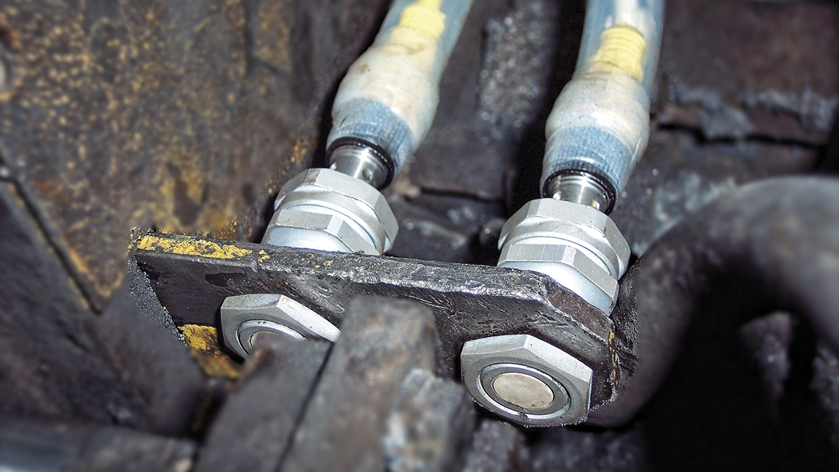 The installation environment will dictate selection of inductive sensor features such as housing material and coating, mounting hardware, cable material, weld field immunity and temperature rating.
Advanced features
For very special applications there are additional selection criteria which include capability or ratings for high pressure, hygiene/washdown, potentially explosive areas, NAMUR, IO-Link/IIoT, plunger probes, and more. These will, however, only rarely factor into inductive welding sensor selection.
Next steps
Once selected and installed, learn from sensor failures and analyze them to reduce failure rates and increase productivity. If a sensor fails, document it, develop an improvement plan and revisit the selection process to address the key issues.
Conclusion
Reliable sensing in welding applications depends on more than choosing a rugged inductive sensor. The best results come from matching the technology to the application area, target, mounting geometry, environmental stressors, electrical interface, protection concept, and cable system.
A strong best-practice approach for applying inductive sensors in automated welding includes four steps:
Select the right sensor
Protect the sensor
Connect the sensor
Learn with continuous improvement. This structured approach simplifies the inductive welding sensor selection and implementation process, leading to higher system performance.
Downloads
-
Weld Select Series Catalog
Keywords
- Sensor technology
- Basics of automation
- Industrial automation
- Inductive sensors
Author

Tom Knauer
Tom Knauer has more than 30 years of industrial automation experience and has presented on condition monitoring and smart manufacturing/IIoT at the Automate Conference, the Assembly Show, IMTS and IME West.
37 Contributions