Real-time speed of IO-Link wired
Are the cycle times too slow?

Reading Time: minutes
IO-Link, which reached more than 35 Mio. installed nodes end of 2022 and depicts a stoning steady yearly growth of 35 %, is now on the verge of becoming the dominant industrial standard for field communication on the factory floor and beyond. Nevertheless, one often hears that despite its many advantages IO-Link is too slow when it come to pure cycle time speed. This critic demands a more careful analysis.
Introduction to IO-Link Version 1.1.3
In this article, we will examine the cycle time of IO-Link wired based on version 1.1.3. This protocol is designed for real-time communication. Therefore, part of the data stream is guaranteed to arrive within a given time frame “the cycle time”. Those data are called “process data” (PD). Besides the cyclic data, the protocol also foresees the possibility to transmit so-called “ on demand data” (OD). The later are exchanged acyclically and without any time regularity. They typically contain configuration, maintenance and events type of information. All of them are not (shall not be) time critical for the user. Additionally, as any communication protocol IO-Link requires a small amount of overhead data to manage the communication channel. Since speed, or better said, cycle time is only critical for PD, we will only consider the amount of PD transmitted data per second as our real-time bandwidth expressed in kbyte/s (i.e. PD amount /second).
Basic IO-Link communication cycle
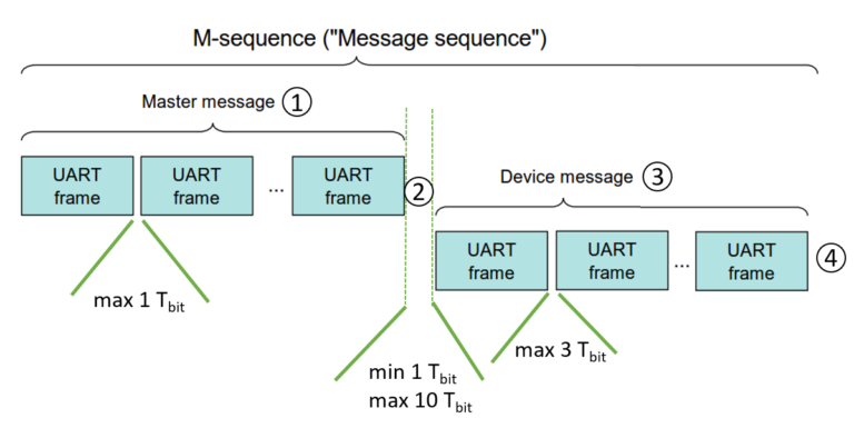
IO-Link wired devices do not act on their own. This means that for a device to send a message, it always requires a request from the master. Thus the basic communication cycle, see Figure 1, is composed with:
the master request,
a waiting time to switch communication direction,
the answer from the device and,
a second waiting time to switch communication direction again.
.png) Basic IO-Link Cycle
Basic IO-Link Cycle
For the calculation of the wired IO-Link cycle time, we assume a “worst case” scenario, meaning that each time the standard gives ranges of values, we always took the largest one. As it can be seen in Figure 2, the time between the UART frames of the message of the master and of the device are 1 Tbit * and 3 Tbit, respectively. As for the waiting time required to switch communication direction, it can reach 10 Tbit.
*Notice: Tbit is the period of time required to transmit 1 single bit.

The value for Tbit is given by the corresponding communication speed of the IO-Link device. The standard offers 3 choices for the serial communication speed “COM1”, “COM2” and “COM3”, with 4.8 kbit/s, 38.4 kbit/s and 230.4 kbit/s, respectively.
COM type | Serial speed [kbit/s] | Tbit [μs] |
COM1 | 4.8 | 208.3 |
COM2 | 38.4 | 26 |
COM3 | 230.4 | 4.3 |
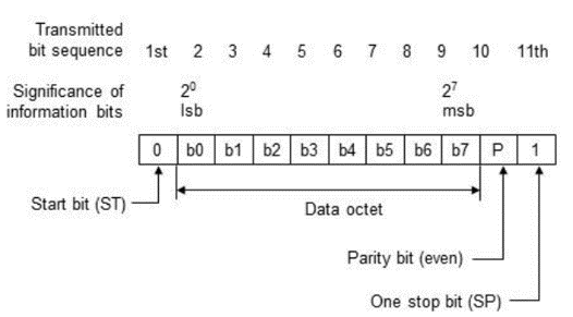
Each UART frame encapsulates 8 bits payload and 3 bits overhead (START, PARITY and STOP). Thus the transmission of 8 bits requires in fact 11 Tbit time.
IO-Link message sequence types
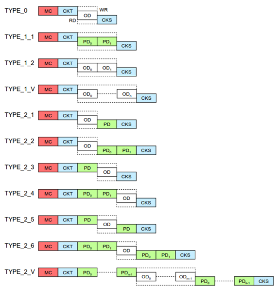
The length of each device and master message is, as expected, influenced by the choice of the message sequence type. In this article, we won’t be using Type 1_x, see Figure 4, because its usage is being limited to IO-Link 1.0 kind of devices. IO-Link 1.0 is, now, not recommended for new designs.
For the real-time bandwidth calculation, PD, in green on Figure 4, transmits the information. Nevertheless the number of OD influence the length of the overall transmission and shall therefore also be taken into account. For the Type 2_1 to Type 2_6 the number of PD and OD octet* are fixed. For Type 2_V the number of PD and OD octet can be configured between 1 and 32 octet for PD and between 1, 2, 8 and 32 octets for OD.
*Notice: Octet = 8 bits, this nomenclature is used in the IO-Link standard.
 M-Sequence types. MC: M-Sequence Control, CKT: Checksum type, PD: Process data, OD: On-demand data, CKS: Check-sum status.
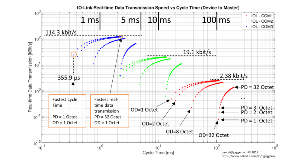
Taking all the above into account, one can generate a plot of the real-time bandwidth versus cycle time. The sum of the time periods (1)+(2)+(3)+(4), depicted in Figure 2, forms the length of one cycle. Thus the real-time bandwidth is given by dividing the length of PD in kbits by the cycle time in seconds. The result is then presented in kbit/s in Figure 5.
For example the largest real-time data transmission is obtained using COM 3 with 1 octet OD and 32 octets PD. Thus from Figure 5, one gets a cycle time of 2.24 ms. Therefore 32*8 bit/2.24 ms = 114.3 kbit/s
 IO-Link real-time data transmission speed.
Conclusion
As expected COM3, dark blue on Figure 5, provides both best performance in term of real-time bandwidth and cycle time.
The fastest cycle time is reached by using Type 2_V with 1 octet of PD and 1 octet of OD. Type 2_1 and Type 2_3 also provide the same performance.
The best real-time bandwidth is achieved by using Type 2_V with 32 octets PD and 1 octet OD.
One other remarkable point is that even using OD with 8 octets and PD with 4 octets IO-Link still reaches a sub millisecond cycle time with COM3.
In conclusion, IO-Link can easily achieve sub millisecond communication cycles, provided that the correct balance between the PD and OD is selected by the device designer.
Keywords
- Efficient production
- Basics of Automation
- Industrial Automation
- Industrial Networking
- Industry 4.0
- IO-Link
- Trends in technology
Author

Balluff GmbH
Our passion for innovative solutions in industrial automation makes us your ideal partner. Balluff is a global leader with more than 100 years of experience. With our expertise, we strengthen your competitive position in the long term.
2 Contributions
Comment
Popular posts
An easy way to remember PNP and NPN sensor wiring
Advantages of inductive proximity sensors in industry
Automation for intralogistics: a practical perspective
Tool Identification in Metalworking
Contact form
Do you have any questions or suggestions? We are at your disposal.
Balluff GmbH
-
Zabergäustraße 8
73765 Neuhausen a.d.F.

